

Hi, and welcome to this video on the wheel and axle!
In this video, we’re going to discuss what a wheel and axle system is, give some real-life examples, and explain how the wheel and axle perform work.
Let’s get started!
What is a Wheel and Axle System?
A wheel and axle is one of six types of simple machines and consists of an outer ring or cylinder called the wheel and an inner ring or cylinder called the axle. These two parts are rigidly connected and move together in the same direction when a force is applied to either the wheel or the axle.
Since the wheel and axle move together, it takes the same amount of time for both to make a full rotation. However, since they have differing circumferences (and radii), a point on the axle moves much slower than a point on the wheel. As such, the point on the axle will cover less distance than the point on the wheel.
Now, recall that work is equal to the force applied to something multiplied by the distance it travels.
Also recall that the input work, \(W_{i}\), must equal the output work, \(W_{o}\), due to the conservation of energy.
But with the wheel and axle, we can apply a small force to the wheel and get a bigger force out of the axle, as long as we apply the force over a longer distance.
What’s important to note here is that, since we are dealing with circular motion, we’re going to use the concept of torque, τ. This means that we’re going to use the radius instead of the distance.
For a wheel and axle, we can keep in mind that
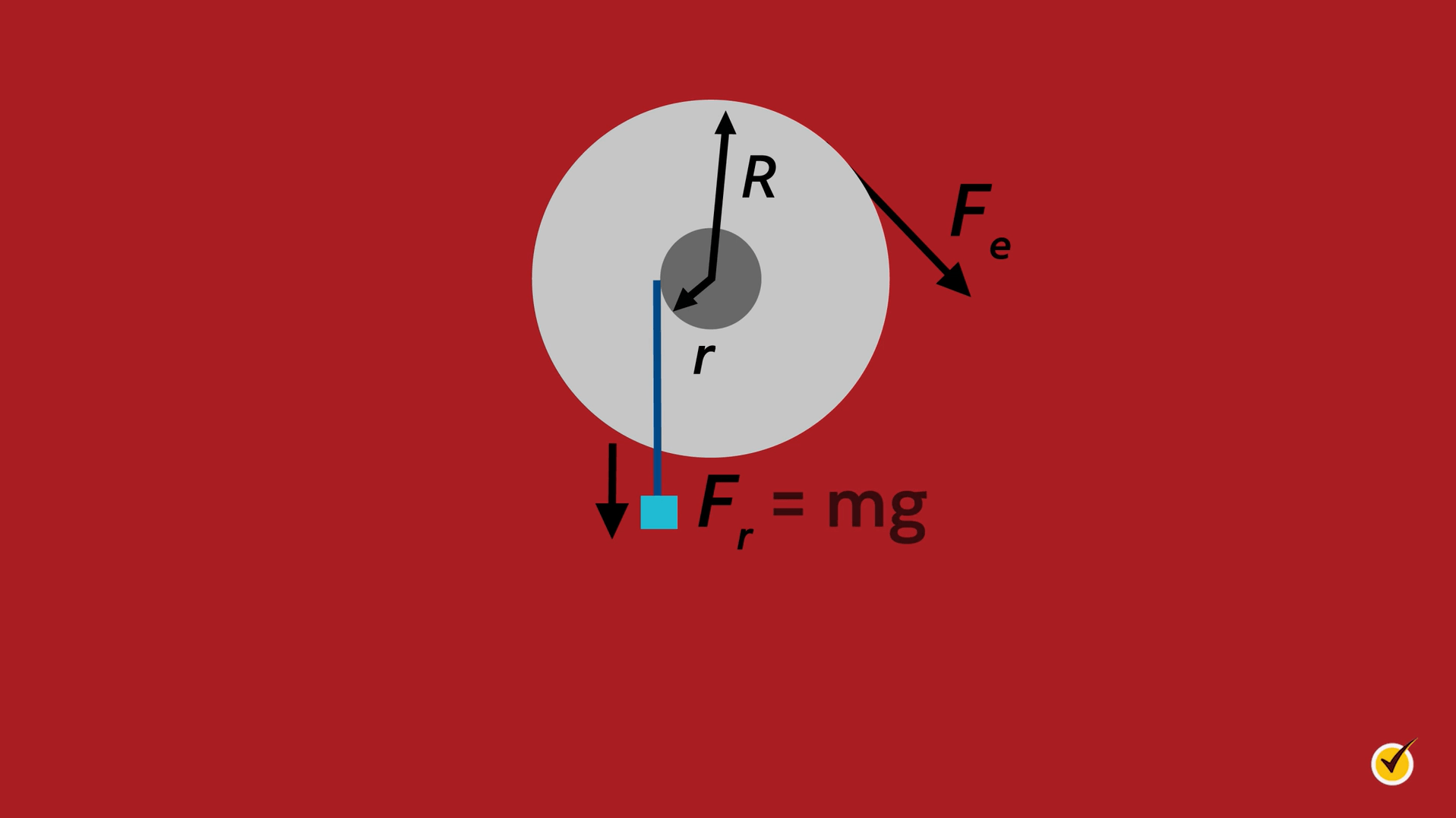
\(F_{w}\) is the force on the wheel with \(R\) as its radius, and \(F_{a}\) is the force on the axle with \(r\) as its radius.
The input force may be applied to the wheel when the output force is supplied by the axle, and since any point on the wheel will travel farther than a point on the axle, the force of the wheel will be smaller in order for the equation to remain true.
Here, we can see where the radii, \(r\) and \(R\), are measured from and we can see two possible forces acting on the system. In this case, the wheel is turned in the direction of \(F_{e}\) to lift the box, whose force is \(F_{r}=mg\).
The mechanical advantage for the wheel and axle is defined using the radii.
This equation gives us an idea of how advantageous the system is or how well it performs. As we can see from the ratio, the bigger the size difference between the two radii, the better it works. So, for a larger wheel, we would need to provide less force to move it but over a longer distance because of its larger radius.
This may be a little confusing, so let’s look at some examples!
Examples
A doorknob is an excellent example of a wheel and axle system.
The knob that we turn with our hands acts as the wheel part of the system, and inside the doorknob, there is an axle that moves the latch so that the door will open properly.
Other similar examples are steering wheels in cars and faucet knobs.
We apply force to the wheel part of these devices, so that the axle moves to accomplish another task in the system with the work that we put in.
On a much larger scale, Ferris wheels are another example of wheel and axle systems!
There is something different about the Ferris wheel that’s important to notice. The input force is actually applied to the axle instead of the wheel. The applied force is used to turn the wheel.
We can see here that the radius of the axle of a Ferris wheel is considerably smaller than the wheel radius. So, the force exerted to move the outer wheel must be higher, but over the small distance of the axle circumference.
It should be mentioned that in a system like this one, the mechanical advantage ratio would be flipped, so \(MA=\frac{r}{R}\).
This makes \(MA <1[/latex], since the axle’s radius is much smaller than the wheel’s. And that’s okay. A Ferris wheel isn’t used to make another function easier, like a doorknob. Instead, a motor must use power to turn the axle in order to move the wheel. Fans work this way as well.
Gears
Now, let’s talk about a special kind of wheel: the gear. Gears use interlocking ‘teeth’ to move other gears, and are often used to change the direction or speed of a system. Let’s take a look at these gears.
We have two interlocking gears of different sizes. If the larger of the two is being turned by an axle in its center which makes it turn counterclockwise, then what will happen to the smaller gear? The smaller gear will start turning in the clockwise direction, and since its circumference is smaller, it will turn faster than the larger gear and with less force (one rotation of the big gear will amount to more than one full rotation of the smaller gear).
This ability can be taken advantage of and used to create a complex machine consisting of multiple simple machines by transferring work between each of the simple machines. Here, the initial work would be on the axle of the large wheel which makes the large axle move and transfers the work to the small gear. And since [latex]W_{i}=W_{o}\), the work transferred will be the same.
There are four basic types of gears:
- Spur gear
- Rack and pinion gear
- Bevel gear
- Worm gear
Spur Gear
The simplest gears are the spur gears, which are generally used to increase or decrease the speed of a device. Spur gears have teeth that are parallel with the axis of the gear and generally lie in the same plane, as shown here.
Rack and Pinion Gear
A rack and pinion gear looks similar to a spur gear, but instead of rotating other gears, the gear engages a rack, which then slides left or right depending on which direction the gear is turning.
These gears are used in the steering systems of many cars.
Bevel Gear Gear
Bevel gears are generally used as the main mechanism in hand drills, transmitting power between two axles spinning at different speeds.
Worm Gear
The fourth type of gear is the worm gear.
Worm gear systems consist of a spur gear and a long cylindrical piece with threading that looks much like a screw without a head. These gears are often used for reducing the speed of a system.
Review
Now that we’ve discussed how wheel and axle machines work and how gears can be used with them, let’s check our understanding with a couple of questions!
1. Where is the input force applied in a bicycle wheel? Would you go faster with bigger or smaller wheels (assuming the same size axle and the same rate of pedaling)?
- On the wheel, bigger wheels
- On the wheel, smaller wheels
- On the axle, bigger wheels
- On the axle, smaller wheels
Through pedaling and with the use of gears, the force is applied to the axles of the wheels in order to make the wheel revolve. If the wheel is bigger and the person still pedals at the same rate (the axle is moving at the same speed in both cases), the bicycle will go faster because the circumference of the wheel is bigger. However, they will need to apply a bigger force to pedal.
2. A screwdriver is another type of wheel and axle. Would the mechanical advantage of a screwdriver be greater than one or less than one?
- <1
- >1
- Equal to 1
The force is applied to the handle of a screwdriver, which makes it the ‘wheel’ part of the system. This means \(MA=R/r\), where \(R\) is the handle radius and r is the axle radius, which is smaller.
That’s all for our video on wheels and axles. Thanks for watching, and happy studying!